The various flowchart symbols available within the Shapes galleries of Microsoft Office applications can represent different concepts. On this page, we show you a visual representation of each of these flowchart symbols along with their names and a brief description.
| Shape | Shape Name | Description |
|---|---|---|
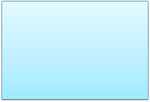 |
Process | The Process (typically a Rectangle) shape shows a process, task, action, or operation. This shape represents something to be done or an action to be taken. Note that the text within the Process shape almost always includes a verb. |
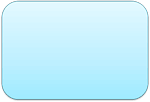 |
Alternate Process | Alternate Process (typically a rounded Rectangle) allows you to specify an alternate process. Compare the rounded edges of this rectangle vs. the sharp corners of the conventional Process shape. Often, this shape is used for an automated activity that happens faster than the conventional Process. |
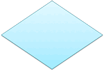 |
Decision | A Decision (typically a Diamond) shape denotes a question or a branch in the flowchart sequence. Most of the time, you see two branches emanating from a Decision shape. These branches are Yes and No responses. Sometimes, you may see a third branch emanating with a Maybe or another response. |
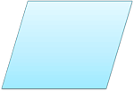 |
Data | A Data shape (typically a Parallelogram) is used to show input or output from a data source. Examples include receiving a report, getting an e-mail, getting an order, receiving data in some format, generating a report, sending an e-mail, faxing a message, etc. |
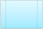 |
Predefined Process | This shape is used for a process that has already been defined elsewhere. This indicates that there is another flowchart available for this predefined process, and you should reference that source for more information. The Predefined Process shape is also known as a Subroutine. It is typically used to simplify complex flowcharts by moving a large part of the flowchart to another flowchart. Optionally, you can then hyperlink this shape to the other flowchart. |
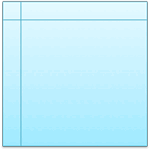 |
Internal Storage | This shape represents data stored, and is used mainly in computer programming flowcharts. Typically refers to data stored in memory. |
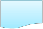 |
Document | A Document or a Report is represented by a rectangle with a curved bottom-left area. Also represents a printed document. |
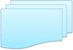 |
Multidocument | This shape is same as Document, but with multiple documents or reports. This can also represent multiple printed documents. |
 |
Terminator | This shape depicts the start or stop point in a process. To designate the start of flowchart, type words like Start or Begin within this shape. |
 |
Preparation | This shape is used to depict a step that involves preparation, such as setting up your equipment or even a process. |
 |
Manual Input | This shape depicts manual input, such as entering data into a computer via a keyboard. |
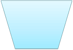 |
Manual Operation | Represented by a Trapezoid shape, this depicts a manual operation. This indicates any operation or adjustment that has to be done manually by the user, as opposed to doing the same activity automatically. |
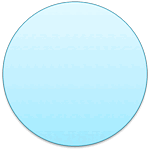 |
Connector | This shape is generally used in complex flowcharts to connect one point of the chart with another without having to draw a line. Typically such shapes may also contain text within the Connector symbol. |
 |
Off-Page Connector | This shape is to show that the flowchart is continued onto another page. A letter or page number in the shape guides you where to go. Note that such Off-Page connectors can be rotated to indicate the direction of the other page. |
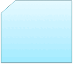 |
Card | This shape depicts an old IBM-computer styled punch card, rarely used in present day flowcharts. |
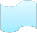 |
Punched Tape | This shape depicted an old computer punched tape input, again rarely used in present day flowcharts. Sometimes, this shape is also called a Paper Tape. |
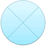 |
Summing Junction | This shape is used when multiple input branches converge into a single process. It is also used as the logical AND. |
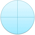 |
Or | This shape performs a logical OR on the input braches. Also, this shape can have multiple output branches. |
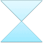 |
Collate | The Collate shape sequences Merge plus Extract. This shape is used to merge multiple processes that result in extracted processes. More often than not, the outcome is a standard format or arrangement. |
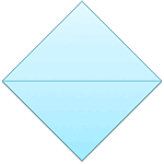 |
Sort | The Sort shape sequences Extract plus Merge. This shape is used to extract a single source to multiple results and then converge them back to a single merge point. More often than not, the outcome is arranging a set of data into a pre-defined order. |
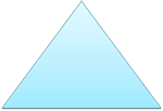 |
Extract | The Extract (split processes) shape removes one or more specific sets of items from a set. Also depicts storage of finished goods. |
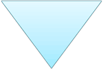 |
Merge | The Merge (storage) shape is used to merge multiple processes into one. Also depicts storage of raw material. |
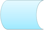 |
Stored Data | This shape represents a general data storage. The data may be stored on a hard drive, magnetic tape, memory card, of any storage device. |
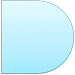 |
Delay | This shape represents a waiting period where no activity is done. This shape is important as the delay may result in adding to the cost of the product or simply delaying the production. Delays should be analyzed to see if they can be minimized or eliminated. |
 |
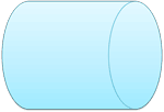
Sequential Access Storage | Sequential Access Storage (magnetic tape) is akin to an old reel of tape representing storage. |
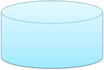 |
Magnetic Disk | This shape depicts a database of any type such as: Microsoft Access, SQL Server, etc. |
 |
Direct Access Storage | A cylinder represents Direct Access Storage. A hard drive is referred to as direct access storage since any sector on the drive can be accessed. |
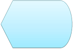 |
Display | This shape refers to the display on a PC, indicating that the information is being displayed to the user. |
Figure 1 below shows some flowchart shapes. Quick, can you identify these shapes? If you need help, look earlier on this page to find representations of these three shapes and what their names are!
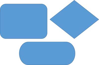
Figure 1: Some flowchart shapes
Reference
https://www.indezine.com/products/powerpoint/learn/flowcharts/flowchart-symbols-what-they-represent.html


